VLSI Interview Question Series
In this series, We will add all the important questions asked in a typical interview focusing on digital design and digital electronics fundamentals. We will also add the solution to all these questions to help you understand. But, we would recommended you to not to see the solution first and solve the questions by yourself. All these questions are typically asked in most of the entry level VLSI interviews.
Q1. Design a circuit that would count 1 every time another counter counts from 0 t0 255.
Ans. This is basically a counter that can count from 0 to 255. Number of states = 256=2*8.
It’s a 8 bit counter. You can simply implement this with D ffs.
Q2. How can you multiply a clock by 2 using only combinational logic?
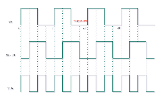
Ans. To multiply a clock inside chips, mostly PLL (mixed-signal block) is used. But, here as the requirement is some combinational logic we need to consider only combinational logic. Multiplying a clock by 2 in frequency means squeeze the +ve clock width by half. (consider 50% duty cycle clock). Considering ideal circuit components, logically we can get the 2X of input frequency by using the below circuit. Shift the input clock by T/4 (where T = time period of input clock ) and apply both clock to the inputs of an XOR gate. XOR gate asserts to logic 1 when both the inputs are not at same logical level i.e the inputs are different. The full circuit diagram and timing diagram is given below.
Q3. Realize a two input AND gate using XOR gate.
Ans. It is not possible to make an AND gate by using XOR gate as it’s not a universal gate.
Logical expression of XOR gate is Y = AB’ + A’B
Also, for XOR gate, when inputs are same the output is 0. Hence, it can’t differentiate between input combinations.
Q4. A 7-bit ring counter has initial states as 0100010. After how many clock cycles it will return to initial state?
Ans. For ring counter, the output is fed back to input as it is. So, it will take exactly 7 cycles to get the same initial state.
Q5. Design a 2:1 MUX using half adder.
Ans. Let’s say the mux inputs are A,B(MSB) and S (select line). The output is Y. Logical expression for a 2:1 MUX is as given below.
Y=A.S’ + B.S
When S=0, mux output is A and when S=1 mux output is B.
Also, we know for a half adder, the sum output can be written as sum = AB’ + A’B which is nothing but an XOR gate. The carry out is AB which is an AND gate.
For XOR gate, when inputs are same/equal output is 0 and when inputs are different output is 1. In other words, when one of inputs at logic 0 then output will be same as input. If one of the inputs is at logic 1 then output will be inverted. This same logic can be used to get the functionality of select line. The below shows how 4 half adders can be used to get the same functionality of a 2:1 MUX. Practically speaking, this is an overkill and useful only for academic problem solving.


