In my previous post RC Circuit Analysis , I have described the fundamentals of simple Analog RC circuit which is the backbone of all other RC circuit combination analysis. I highly recommend to go through the previous post RC Circuit Analysis to get familiarize with fundamentals of RC analysis.
In this post we are going discuss the behaviour of 2R-1C RC circuit excited with step voltage input. In our analysis all the components are considered ideal.
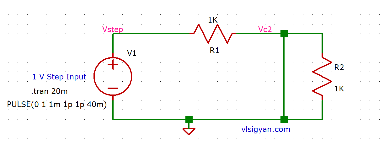
The 2R-1C combination RC circuit is given below.

From our earlier analysis in RC Circuit Analysis , we are aware that we need to find out the voltage across capacitor and current flowing through it at time t=0+ and t=infinity.
Analysis at time t=0+
Now, for the above circuit, before application of input voltage capacitors is fully discharged (voltage across it = 0 v). After application of step voltage, from the fundamental property of capacitors, the capacitor will prevent the sudden change of the voltage across it and will try to remain at voltage=0.
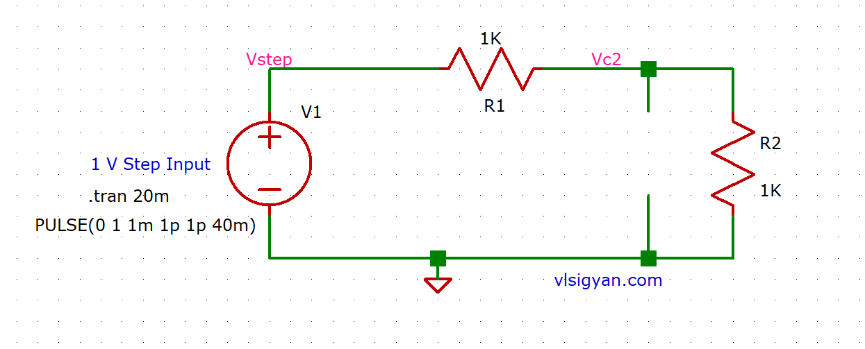
From our previous analysis, at  the circuit will look like below.
In the above circuit, we can see capacitor is behaving like a short circuit. This gives us the voltage across capacitor at is zero. So, the current that flows through the circuit is  . The voltage across resistor
  , is same as input voltage
  .
.
Analysis at time t=infinity
From our previous post with 1R-1C circuit, we know that when capacitor is fully charged it acts like an open circuit and no current flows through it. Keeping this in mind, at t=infinity, let’s say capacitor  charges fully, behaves as an open circuit and current flowing through is zero. The circuit becomes a series combination of two resistors and input voltage source at t=infinity.
From voltage divider rule, the voltage across capacitor C2 ( or resistor R2, both are in parallel) can be written as below-

The time constant of the circuit can be calculated by shorting the voltage source and calculating  and
and  .
.
Here, 
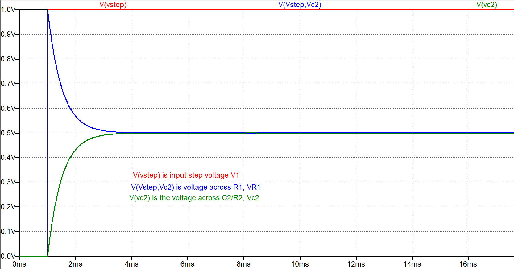
Below shows the simulation result in LTspice.

Feel free to comment if you have any questions/suggestions.
Check All the RC circuit related posts.