In a series of posts, we are going to discuss about various rc circuit related questions that are asked in analog design engineer job interviews. RC circuits are fundamental building block of analog circuit design. Good grip on these is a very good skill to possess. All the electronics engineers aiming to get into entry level analog vlsi design jobs should prepare rc circuits thoroughly as they are definitely going to be tested their rc circuit analysis skills.
In this post, we will try to discuss various RC circuit combinations with step/ramp etc. as voltage/current input. All components are assumed ideal. We have used LTSpice spice simulator to simulate the RC circuits.
Before we jump into the circuits, let’s note down some general know how of some unique properties of a capacitor.
- Capacitor prevents sudden change of voltage across it. It needs time to change the voltage across it. Basic capacitor voltage equation is given below.

- As capacitor prevents sudden change of voltage, ( can be seen from the above equation as current flowing through a capacitor depends on time derivative of voltage, that means if voltage changes in no time dt->0 then only it can change its state abruptly) it holds its state before and after the state change. So, if a capacitor is at discharged state ( voltage across capacitor,
 ) at
) at  time, then after applying voltage at t=0+ voltage across it still be at
  . Therefore,
- At steady state, that is when capacitor is fully charged the current flowing through the capacitor is zero i.e it behaves like an open circuit. This can be verified by putting constant voltage in the above equation. This gives current,
 which means it acts like an open circuit.
R-C Circuit With Step Voltage Input
Basic circuit is show below with R1=10K Ohm and C1=1u Farad and input voltage is a step voltage with strength=1V.
At ![]() , capacitor will behave like a short circuit and all the current will flow through it. Here, the magnitude of the current is
, capacitor will behave like a short circuit and all the current will flow through it. Here, the magnitude of the current is ![]() . So, initially the current is a constant current. The rate of change of voltage ( here increment) across capacitor is given by
. So, initially the current is a constant current. The rate of change of voltage ( here increment) across capacitor is given by
![]()
Based on the above, we can say that initially, capacitor will charge linearly but as the capacitor starts having voltage across it the current flowing through the circuit will now depend on the voltage across the capacitor also. So, ![]() . As capacitor charges, difference between
. As capacitor charges, difference between ![]() will be keep on reducing and when the capacitor charges fully to the input voltage the current will become zero, i.e capacitor will behave like an open circuit.
will be keep on reducing and when the capacitor charges fully to the input voltage the current will become zero, i.e capacitor will behave like an open circuit.
RC Circuit Plot
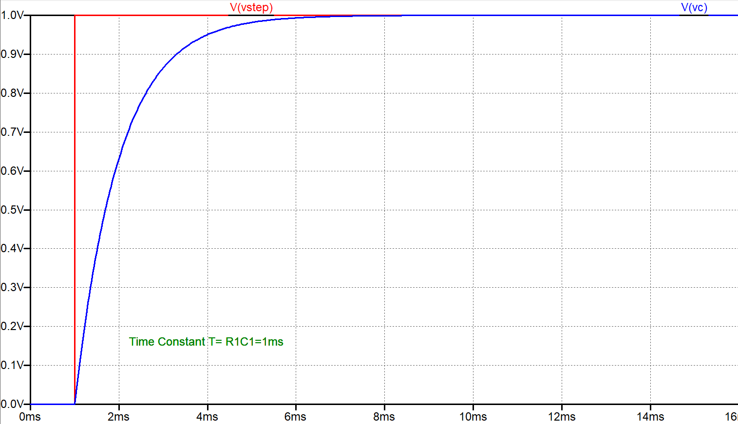
Input Step Voltage vs Voltage Across Capacitor Plot
The time constant of the circuit is R1*C1=1ms. To find the time constant of a RC circuit use the below procedure.
- Desensitize the circuit. That means replace all the voltage sources with short circuit ( voltage=0) and all the current sources with open circuit ( current=0).
- Calculate the effective capacitance of the circuit ( combining serial/parallel caps)
- Calculate the Thevenin equivalent resistance of the circuit.
- Multiply both to get the time constant of a RC circuit.
Intuitively, we should only consider those capacitance/resistance that affects the charging or discharging of the capacitor. So, depending on the situation, for a given circuit, there may be different time constant for charging and discharging cases.
As a thumb rule, RC circuit takes 5*Time Constant to attain the steady state.
Plot Capacitor Current
From plot one can see, the initial current is ![]() . As
. As ![]() increases this current reduces exponentially and tends to zero.
increases this current reduces exponentially and tends to zero.
In this circuit, the capacitor and resistor are in series hence the same current flows through the capacitor and resistor. The current profiles are same.
For a RC circuit, we can write express the voltage and current equations of the circuit if we know the time constant of the circuit and voltage and current numbers at a ![]() and
and ![]() .
.
In general, the voltage at time ![]() can be expressed as,
can be expressed as,
![]()
For this RC circuit, initial voltage= 0, final voltage is equal to the input step voltage amplitude i,e 1 V and time constant is R1*C1=1ms. So, the above equation can be written as below,
![]()
Below Posts discuss different combination of RC circuits for analog interview.


